Hardware
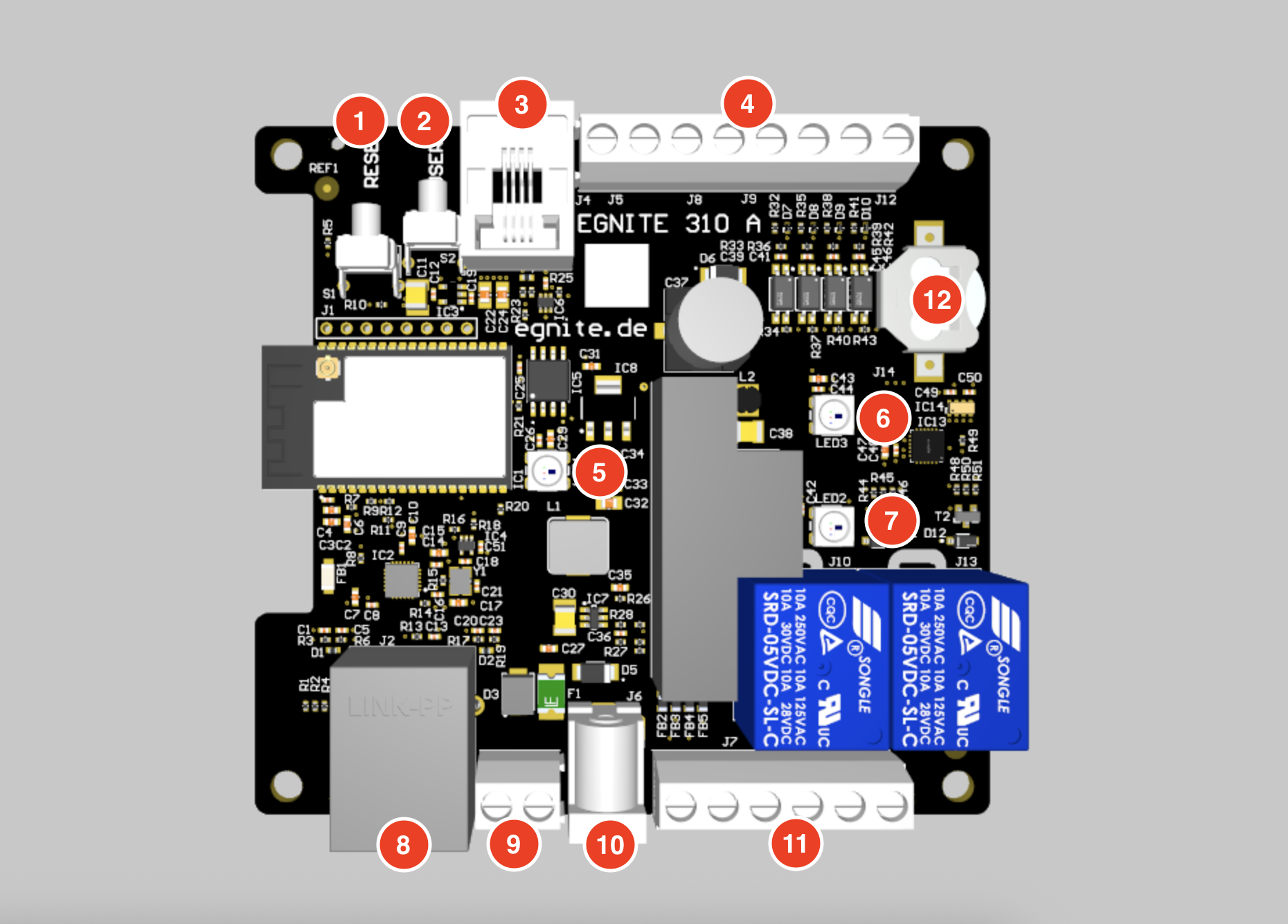
Device Overview
Prerequisites
Reset Button
Reset the device
Push and release immediatly, to reset the device.
Switch Firmware
In addition to the currently active firmware, the device has a second fallback firmware stored. It is possible to switch between those two slots:
- Before supplying the device with power, press and hold the reset button.
- The status LED should start to blink fast in red.
- After a short time the status LED should stay red permanently. In this state, release the reset button.
- The firmware slot should now be switched.
Delete configuration
In case the configuration is corrupted in a fashion, that you can not reach the web interface, it is possible to reset the configuration to factory settings with the help of the reset button:
- Before supplying the device with power, press and hold the reset button.
- The status LED should start to blink fast in red.
- After a short time the status LED should stay red permanently.
- After a another delay the status LED should start to blink fast in orange.
- After a short time the status LED should stay orange permanently. In this state, release the reset button.
- The configuration should now be reset.
User Button
While this button exists, it does not do anything at this time.
Sensor Port
Use this RJ11 port, to connect to egnite 500 Series sensors via the 1-Wire interface.
Refer to the
- egnite 500 Series docs for details on the hardware setup and the
- Sensors docs page for the software configuration.
Additional sensors can be attached by daisy chaining - the sensors of the egnite 500 series provide 2 RJ11 ports (which can be used interchangably).
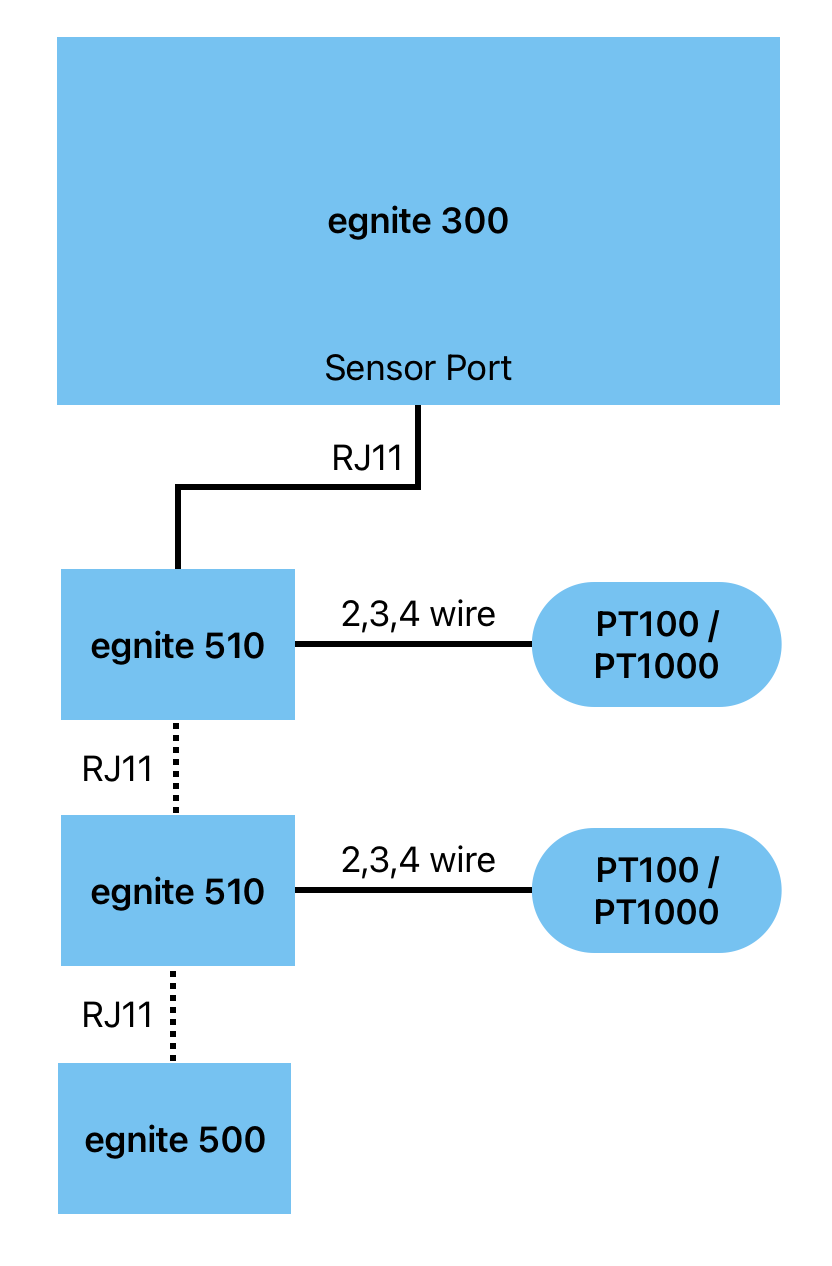
The maximum physical length of the sensor chain to work reliably is
- 30m in series and
- 10m in wye/star connection.
RJ11 Pinout
| Pin 1 | Pin 2 | Pin 3 | Pin 4 | Pin 5 | Pin 6 |
|---|---|---|---|---|---|
| GND | GND | 1-Wire | GND | +5V | +5V |
The maximum number of egnite 500 devices you can chain depends on many factors.
An upper bound for egnite 310 for example is, that it supports up to 16 sensors.
Plug in only sensors of the egnite 500 series with the provided RJ11 cable.
Other devices using this connector are not electrically complatible with this device and plugging them in may lead to damage or destruction of both devices.
Compatible sensors to use with this device are offered separately as part of the egnite 500 Series.
Refer to the egnite 500 Series documentation for further details on available sensors, specifications and hardware setup.
// TODO marketing site, shop link, sensortypen
Digital Inputs screw terminal
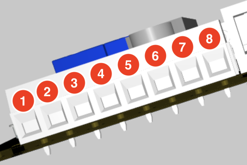
The device provides 4 digital inputs working as dry contact inputs, where 2 screw terminals belong to each input.
A contact input is an input that detects whether an external switch or relay contact is open or closed, without supplying any voltage itself. It is used to read simple on/off states from devices like switches, buttons, or relays.
Thus an input is recognized as closed / active when terminals A and B are electrically connected, else it is registered as open / inactive.
The digital input screw terminal block consists of 8 terminals, named pin 1 to pin 8.
| Pin | Function | Description |
|---|---|---|
| 1 | Input 1 - A | Contact input terminal A |
| 2 | Input 1 - B | Contact input terminal B |
| 3 | Input 2 - A | Contact input terminal A |
| 4 | Input 2 - B | Contact input terminal B |
| 5 | Input 3 - A | Contact input terminal A |
| 6 | Input 3 - B | Contact input terminal B |
| 7 | Input 4 - A | Contact input terminal A |
| 8 | Input 4 - B | Contact input terminal B |
Status LED
| Color | State | Meaning |
|---|---|---|
| Green | Blinking every 10s | Normal state |
| Red | Blinking every 1s | Sensor or Watchdog Alarm (Abnormal condition) |
| Red | Permanently | Potential Firmware Error |
Output 1 LED
Indicates that Digital Output 1 is
- active by lighting up in green
- inactive by lighting up in red
Output 2 LED
Indicates that Digital Output 2 is
- active by lighting up in green
- inactive by lighting up in red
Ethernet port
Use this RJ45 port to connect the device to your Ethernet LAN.
PoE - Power over Ethernet
The device supports PoE (IEEE 802.3af, Class 0) over this connector. This means, that the device can be power supplied via the ethernet port, instead of the other two options below.
Note, that you need additional hardware such as a PoE switch to use this feature.
Power supply screw terminal
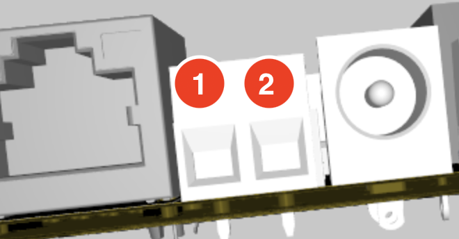
Use this screw terminal to power the device with a suitable bench power supply.
| Pin | Value |
|---|---|
| 1 | Ground |
| 2 | +V (9-24V) |
| Pin 2 | Value |
|---|---|
| Minimum - Maximum Voltage | 9–24 V |
| Power Consumption | 18 W |
When using the screm terminals for power supply, do NOT plug in the power supply coaxial port.
Power supply coaxial port
Use the coaxial barrel port to supply the device with an external power adapter, which can be purchased from egnite.
The provided power adapter oprates at 12 V and 1.5 A.
| Contact | Diameter |
|---|---|
| Inside (V+) | 2.5mm |
| Outside (GND) | 6.4mm |
| Value | |
|---|---|
| Minimum - Maximum Voltage | 9–24 V |
| Power Consumption | 18 W |
Digital Outputs screw terminal
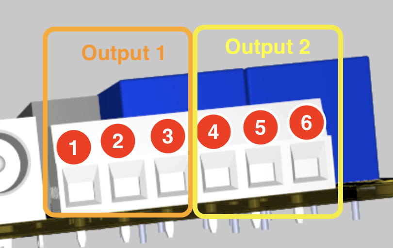
The device provides 2 digital outputs, where 3 screw terminals belong to each output.
The digital outputs screw terminal block consists of 6 terminals, named pin 1 to pin 6.
Pin 1-3 belong to the relay of the first output. Pin 4-6 belong to the relay of the second output.
The relays each have 3 contact pins, for operating as either normally closed (NC) or normally open (NO).
| Pin | Function | Description |
|---|---|---|
| 1 | Output 1 - NC | Normally Closed — connected to COM when relay / digital output is OFF |
| 2 | Output 1 - COM | Common contact |
| 3 | Output 1 - NO | Normally Open — connected to COM when relay / digital output is ON |
| 4 | Output 2 - NC | Normally Closed — connected to COM when relay / digital output is OFF |
| 5 | Output 2 - COM | Common contact |
| 6 | Output 2 - NO | Normally Open — connected to COM when relay / digital output is ON |
| Between (COM and NC) & (COM and NO) | Value |
|---|---|
| Maximum Voltage | 50 V |
| Maximum Current | 10 A |
TODO: Pinbelegung überprüfen
Buffer Battery
The battery is used to provide the internal realtime clock with electricity, when the device is not power supplied.
(Replacement) Battery type: Renata CR1225