Sensors
In the context of this device and documentation, a sensor refers to a 1-Wire hardware sensor connected to the device, as well as its digital representation.
The egnite 310 supports connecting up to 10 1-Wire sensors.
Compatible sensors to use with this device are offered as part of the egnite 500 Series.
Refer to the egnite 500 Series documentation for further details on available sensors, specifications and hardware setup.
To configure the sensors connected to the device, please navigate to Sensors from the main menu in the Peripherals section.

The Sensors main page presents an overview table, where each row represents one sensor.

To navigate to the configuration page for a specific sensor, click on the corresponding row.
Adding and removing new sensors
Hardware Setup
Refer to the documentation of the specific sensor of the egnite 500 Series documentation you are going to connect.
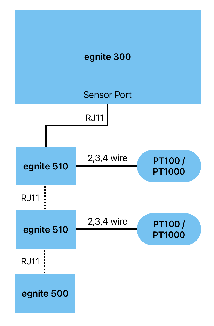
This will guide you with connecting the sensor to the sensor port (RJ11) of this device or alternatively to the seconds RJ11 port of another sensor of the same series (daisy chaining).
Once the sensor is physically connected by the RJ11 cable to the device, it can be configured in software in the web interface.
Adding a sensor
Click the button on the top right of the Sensors main page.
The newly connected sensor should appear as an additional row in the overview table.
To configure it, follow the instructions in section Configuring a sensor
Removing a sensor
To remove a sensor, detach the sensor physically. After that either click the Button or reboot the device.
When you return to the list of sensors, a Button should be visible in the respective row in the overview table. Click on it to remove the sensor from the list.
Configuring a sensor
In the sensors overview table, click on the row of the sensor you would like to configure.
This will open the detail configuration page, as shown below.

Name
Choose a descriptive name for the sensor.
While not relevant to the functionality, this name will be displayed on several locations of the web interface.
If you leave this field blank, a default name will be displayed instead.
Group
Optionally enter a string as the name for the group, this peripheral should belong to.
If you use the same group name for other peripherals (sensors, digital I/Os, watchdogs), those can be shown and filtered by their group on the dashboard.
Unit
Choose a measurement unit from the dropdown, that suits the sensor.
If your desired unit is not available in the dropdown, choose Custom and enter a descriptive custom unit string in the input field next to the dropdown.
For Kelvin and Fahrenheit, the value will be automatically converted from Celsius.
Normal Range
The normal range determines what should be considered acceptable sensor values.
-
Minimum: If the sensor value gets lower than the provided Minimum threshold, the sensor is considered in a value too low state, which is displayed on the dashboard and can trigger warning notifications (see below).
-
Maximum: If the sensor value gets higher than the provided Maximum threshold, the sensor is considered in a value too high state, which is displayed on the dashboard and can trigger warning notifications (see below).
-
Hysteresis: A buffer zone around the minimum and maximum thresholds, to prevent triggering entering and leaving the threshold value, when the value fluctuates around those thresholds.
Transformation
This specifies a linear transformation, which gets continuously applied to the current sensor value, where
- Offset is a number that gets added to the value
- Gain is a number that gets multiplied to the value.
Notifications
When the current sensor value leaves or reenters the normal range (see above), the device can emit notifications to make the user aware.
Check one or multiple of the checkboxes, which stand for the channel(s), over which the notifications get sent. Multiple channels can be activated simultaneously.
The device sends an email.
The exact text of the emails can be customized by supplying or editing a template on the email configuration page.
Email Configuration page- SNMP Trap
The device sends a SNMP trap.
SNMP Configuration page- MQTT Message
The device sends a MQTT message.
MQTT Configuration page- Activation of output 1
- The device activates digital output 1.
- Activation of output 2
- The device activates digital output 2.
Please note, that for
- Email (Configuration page)
- SNMP Trap (Configuration page)
- MQTT Message (Configuration page)
the respective interfaces have to be configured and enabled through their configuration pages.
Also refer to the Notifications docs page.
Box2Box actions
Similar to notifications, when the Box2Box Feature is enabled, the device can control an digital output on another device, when an events occurs with the peripheral.
The corresponding checkboxes are only visible, after the Box2Box feature has been enabled.
// TODO SCREEN
Check one or multiple of the checkboxes, which stand for the output(s), of the controlled device. Multiple outputs can be controlled simultaneously.
Save the configuration
After filling in the form, click on at the bottom of the page, to persist the configuration.
The sensor is now configured and can be used.
Visit the Dashboard to monitor real time and historical values.
Updating sensor firmware
The firmware of the sensor (e.g. egnite 510) can be updated, similar to the firmware of the device.
Download a Sensor Firmware Image
egnite will regulary provide updates to the firmware in form of firmware image files on this website:
https://www.egnite.de/support/firmware/
The firmware image will be a file with a .xmu extension.
After downloading a sensor firmware image you can upload it to the sensor as described below.
Upload Firmware

-
On the sensor configuration page, click on the Sensor Firmware link on the left side of the page as shown on the screenshot above.
-
In the Upload Sensor Firmware section, click on Choose file and select the firmware image file (.xmu) from your local file system.
Alternatively drag the image file from your file manager into the area with a dashed border.
The filename should now be displayed in the section.

- Click the button.
The device will install the provided firmware on the sensor. This will take approx. 20 seconds.
After uploading and installing the new firmware the page will reload.
To verify the installation you can compare the Firmware Name and Version as displayed under Installed firmware at the left of the upload form.
In case that after a sensor firmware update the sensor(s) do not show in the list of sensors, please repeat the procedure described in Adding a sensor.
Additionally you can try rebooting the device.
If the problem persists, consider reaching out to egnite support, ideally referencing the information displayed under Installed firmware and Installed Updater, as well as the name of the firmware image file (.xmu).
1-Wire Device Details (optional)

The section above the Upload Sensor Firmware section displays additional information about the sensor device.
This can be useful for troubleshooting.
As sensor devices of the egnite 500 series operate as 1-Wire client devices, the 1-Wire serial number is displayed.
If a device of the egnite 500 series combines multiple sensors, these still act as a single 1-Wire device.
On the right side of the section under Corresponding Sensors, you will find a list of sensors that are associated with that 1-Wire device.
Troubleshooting
Error while scanning for sensors
Make sure, that the hardware wiring of the sensor is as described on the Hardware docs page, as well as in the docs of the specific sensor device you are using from the egnite 500 Series documentation.
Also ensure, that you are using the provided RJ11 cable. Not all cables are compatible, since some have twisted wire cores in contrast to others.
Sensor error codes
In case of a problem with the sensor hardware or firmware, an error code might be displayed on the Peripherals Status table on the dashboard.
Some common error codes and their meaning are:
| Error code | Meaning |
|---|---|
3A04, 3A11 | Sensor not found / does not answer over 1-Wire. |
3A02 | Updater is running on Sensor. Maybe the last firmware update has been interrupted or did not work. |
4B18 | The wrong firmware file was used for this device. |
4B09, 4B1B, 4B1C | A firmware checksum is wrong. The firmware file could be corrupted. |
B001 | Sensor not yet initialized. This happens when the sensor is queried directly at start. |
B2xx | Error for PT sensor. Maybe broken or shorted wire. |
A10x | Invalid sensor firmware. It could be the wrong firmware file or a corruption. |
If you encounter a problem with a sensor and observe an error code not listed above, reach out to egnite for further assistasnce.